Installation Instructions
DANGER
Failure to heed the following will result in injury or death.
- Deactivate power while routing wiring to control board.
- RISK OF ELECTRICAL SHOCK FROM ENERGY STORED IN CAPACITORS - MODELS EQUIPPED WITH VARIABLE FREQUENCY COMPRESSOR DRIVES STORE ELECTRICITY EVEN AFTER THE POWER HAS BEEN DEACTIVATED AT THE POWER BREAKER. Wait for 2 minutes after the shut down of equipment before servicing.
- This section is only for qualified installers who are familiar with the swimming pool and spa safety standards.
- The installer must be familiar with service industry techniques.
- Follow all National Electric Codes (NEC) and / or State and Local guidelines.
NOTICE
Failure to heed the following may result in damage to equipment.
- Insure a proper electrical ground between power control board and heat pump.
- To permit proper air circulation, the device must be mounted at least 12 inches (30 cm) about ground level or any other air flow obstruction.
- Warranties may be voided if the equipment has been improperly installed. Failure to properly operate, maintain, or repair the device may void the factory warranty.
- Do not attempt to “hot swap” connections with power to the device. Damage to equipment will occur and is not covered by warranty.
STEP 1 - Choose a Mounting Location:
- When selecting a location, choose a flat, stable, vertical surface to mount the relay center.
- DO NOT attach the relay center onto the sides of the Heat Pump or any other equipment.
- Allow enough clearance for electrical conduit and connections at the bottom of the enclosure.
STEP 2 - Install Relays Inside Relay Box Enclosure:
- Open the relay enclosure box.
- Install relays to the inside of the enclosure.
- The kit comes with two relays.
- Mounting hardware and connectors for four additional relays are also included. Retain these parts for future use.
STEP 3 - Mount the Relay Center:
- Mount the relay center using the hardware provided.
- Using a small level can be helpful for proper alignment.
- For concrete/ masonry surfaces a 1/4" masonry bit is required.
STEP 4 - Mount Expansion Board in Heat Pump:
- Disconnect all power to the heat pump and any connected devices. Use a test meter to confirm power is off and capacitors are discharged.
- Use Expansion Board Installation Instructions (LTP0215) to mount the expansion board inside the heat pump.
- Connect expansion board cable to the expansion board and heat pump control board.
STEP 5 - Connect Devices to Relays:
- Connect device wiring to relay connection points (line and load) using properly sized wire for the device being controlled.
- See device instructions for connection points.
STEP 6 - Connect Relays to Heat Pump Expansion Board:
22 gauge minimum, 2 conductor, outdoor rated wire is provided by the installer. Follow all local codes pertaining to routing low voltage control wiring.

- Route the appropriate number of control wires (one 2 conductor wire per relay used) between the relay center and the heat pump control panel.
- Route the wiring so that it will not be stepped on or damaged by be lawn maintenance or similar equipment that could cause damage.
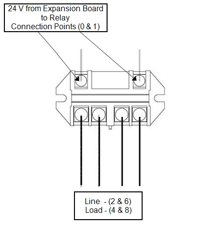
- Strip back and connect wiring to the relay coil at connection point "0" and "1" on each relay.
- Inside the heat pump electrical panel use the inline wire connectors (provided), to attach a relay connector (provided).
- Attach the relay connectors to the expansion board terminals "A"-"F".
STEP 7 - Programming:
- Reconnect all AC power on the device, heat pump, and connected devices.
- Program relays to be used as needed on the heat pump.
- See AquaCal® External Expansion Board Upgrade manual (LTP0167).
- Test that all equipment operates as expected. Then re-attached all access plates.
- Cable manage all wires and cords leading to and from equipment to prevent equipment damage.
Additional Documentation:
Recommended Relays (AquaCal® Part # STK0257) - (up to six relays will fit in the relay center)
Recommmended Relays

Relay Center Schematic
